Smalltalk80LanguageImplementation:Chapter 18
- Chapter 18 Graphics Kernel
Graphics Kernel
Object

    Magnitude
        Character
        Date
        Time

        Number
            Float
            Fraction
            Integer
                LargeNegativeInteger
                LargePositiveInteger
                SmallInteger

        LookupKey
            Association

    Link

        Process

    Collection

        SequenceableCollection
            LinkedList

                Semaphore

            ArrayedCollection
                Array

                Bitmap***
                    DisplayBitmap***

                RunArray
                String
                    Symbol
                Text
                ByteArray

            Interval
            OrderedCollection
                SortedCollection
        Bag
        MappedCollection
        Set
            Dictionary
                IdentifyDictionary

    Stream
        PositionableStream
            ReadStream
            WriteStream
                ReadWriteStream
                    ExternalStream
                        FileStream

        Random

    File
    FileDirectory
    FilePage

    UndefinedObject
    Boolean
        False
        True

    ProcessorScheduler
    Delay
    SharedQueue

    Behavior
        ClassDescription
            Class
            MetaClass

    Point***
    Rectangle***
    BitBit***
        CharacterScanner***

        Pen

    DisplayObject
        DisplayMedium
            Form
                Cursor
                DisplayScreen
        InfiniteForm
        OpaqueForm
        Path
            Arc
                Circle
            Curve
            Line
            LinearFit
            Spline
Graphical Representation
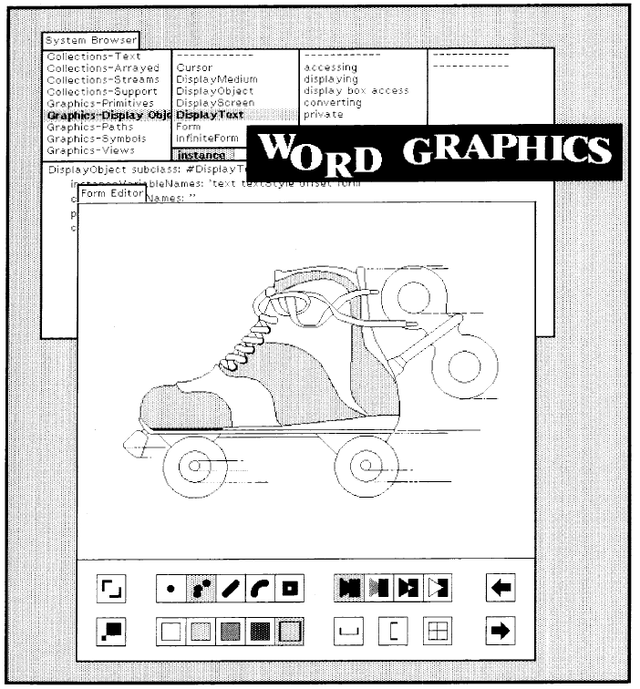
Figure 18.1 shows a view of the display screen for a Smalltalk-80 system. It illustrates the wide range of graphical idiom available to the system. Rectangular areas of arbitrary size are filled with white, black, and halftone patterns. Text, in various typefaces, is placed on the screen from stored images of the individual characters. Halftone shades are "brushed" by the user to create freehand paintings. Moreover, although not shown on the printed page, images on the display can be moved or sequenced in time to provide animation.
The example interaction with the system given in the previous chapter illustrated some of the ways in which objects can be observed and manipulated graphically. Meaningful presentation of objects in the system demands maximum control over the display medium. One approach that provides the necessary flexibility is to allow the brightness of every discernible point in the displayed image to be independently controlled. An implementation of this approach is a contiguous block of storage in which the setting of each bit is mapped into the illumination of a corresponding picture element, or pixel, when displaying the image. The block of storage is referred to as a bitmap. This type of display is called a bitmapped display. The simplest form of bitmap allows only two brightness levels, white and black, corresponding to the stored bit values 0 or 1 respectively. The Smalltalk-80 graphics system is built around this model of a display medium.
Graphical Storage
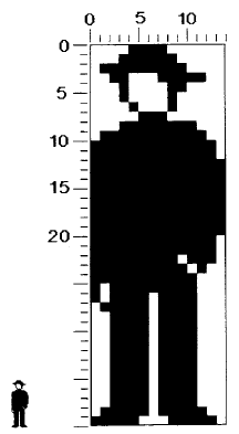
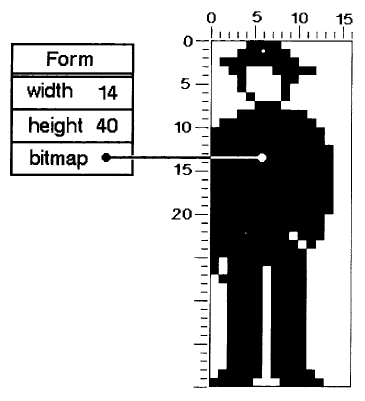
Images are represented by instances of class Form. A Form has height and width, and a bitmap, which indicates the white and black regions of the particular image being represented. Consider, for example, the man-shape in Figure 18.2. The height of the Form is 40, its width is 14, and its appearance is described by the pattern of ones and zeros (shown as light and dark squares) in its bitmap. The height and width of the Form serve to impose the appropriate two-dimensional ordering on the otherwise unstructured data in the bitmap. We shall return to the representation of Forms in more detail later in this chapter.
New Forms are created by combining several Forms. The freehand drawing in the center of Figure 18.1 is an example of a large Form that was created by combining and repeating several Forms that serve as "paint brushes" in a Smalltalk-80 application system. The text in Figure 18.1 is a structured combination of Forms representing characters.
A Form can be presented to the display hardware as a buffer in memory of the actual data or of the image to be shown on a display screen. Since the interface to the hardware is through a Form, there is no difference between combining images internally and displaying them on the screen. Animation can be displayed smoothly by using one Form as the display Form while the next image to be displayed is prepared in a second Form. As each image is completed, the two Forms exchange roles, causing the new image to be displayed and making the Form with the old image available for building yet another image in the sequence.
The Forms used as buffers for data to be shown on the display screen are instances of class DisplayScreen, a subclass of Form. Contiguous storage of bits is provided by instances of class Bitmap. DisplayScreen's bitmap is an instance of DisplayBitmap, a subclass of Bitmap. DisplayScreen and DisplayBitmap provide protocol specific to the actual hardware and to the fact that the Form represents the whole display screen rather than potential parts of it.
Graphical Manipulation
A basic operation on Forms, referred to as BitBlt, supports a wide range of graphical presentation. All text and graphic objects in the system are created and modified using this single graphical operation. The name "BitBlt" derives from the generalization of data transfer to arbitrary bit locations, or pixels. One of the first computers on which a Smalltalk system was implemented had an instruction called BLT for block transfer of 16-bit words, and so "bit block transfer" became known as BitBlt.
Operations are represented by messages to objects. So BitBlt could have been implemented with a message to class Form. However, because BitBlts are fairly complicated operations to specify, they are represented by objects. These objects are instances of the class named BitBlt. The basic operation is performed by sending an appropriately initialized instance of BitBlt the message copyBits. The BitBlt operation is intentionally a very general operation, although most applications of it are graphically simple, such as "move this rectangle of pixels from here to there."
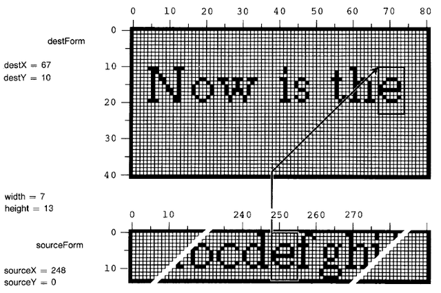
Figure 18.3 illustrates the process of copying a character of text into a region on the display. This operation will serve to illustrate most of the characteristics of BitBlt that are introduced in the remainder of this section.
Source and Destination Forms
The BitBlt copy operation involves two Forms, a source and a destination. The source in the example in Figure 18.3 is a font containing a set of character glyphs depicted in some uniform style and scale, and packed together horizontally. The destination in the example is assumed to be a Form that is used as the display buffer. Pixels are copied out of the source and stored into the destination. The width and height of the transfer correspond to the character size. The source x and y coordinates give the character's location in the font, and the destination coordinates specify the position on the display where its copy will appear.
Clipping Rectangle
BitBlt includes in its specification a rectangular area which limits the region of the destination that can be affected by its operation, independent of the other destination parameters. We call this area the clipping rectangle. Often it is desirable to display a partial window onto larger scenes, and the clipping rectangle ensures that all picture elements fall inside the bounds of the window. By its inclusion in the BitBlt primitive, the clipping function can be done efficiently and in one place, rather than being replicated in all application programs.
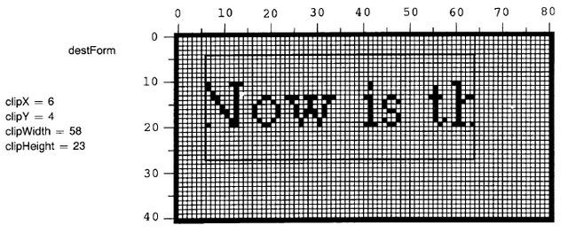
Figure 18.4 illustrates the result of imposing a clipping rectangle on the example of Figure 18.3. Pixels that would have been placed outside the clipping rectangle (the left edge of the "N" and half of the word "the") have not been transferred. Had there been other characters that fell above or below this rectangle, they would have been similarly clipped.
HalfTone Form
Often it is desirable to fill areas with a regular pattern that provides the effect of gray tone or texture. To this end, BitBlt provides for reference to a third Form containing the desired pattern. This Form is referred to as a halftone or mask. It is restricted to have height and width of 16. When halftoning is specified, this pattern is effectively repeated every 16 units horizontally and vertically over the entire destination.
There are four "modes" of supplying pixels from the source and halftone controlled by supplying nil for the source form or the halftone form:
- no source, no halftone (supplies solid black)
- halftone only (supplies halftone pattern)
- source only (supplies source pixels)
- source AND halftone (supplies source bits masked by halftone pattern)
Figure 18.5 illustrates the effect of these four modes with the same source and destination and a regular gray halftone.
Combination Rule
The examples above have all determined the new contents of the destination based only on the source and halftone, storing directly into the destination. The previous contents of the destination can also be taken into account in determining the result of the copying.
There are 16 possible rules for combining each source element S with the corresponding destination element D to produce the new destination element D'. Each rule must specify a white or black result for each of the four cases of source being white or black, and destination being white or black.
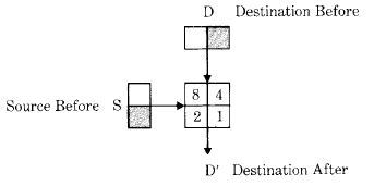
Figure 18.6 shows a box with four cells corresponding to the four cases encountered when combining source S and destination D. For instance, the cell numbered 2 corresponds to the case where the source was black and the destination was white. By appropriately filling the four cells with white or black, the box can be made to depict any combination rule. The numbers in the four cells map the rule as depicted graphically to the integer value which selects that rule. For example, to specify that the result should be black wherever the source or destination (or both) was black, we would blacken the cells numbered 4, 2, and 1. The associated integer for specifying that rule is the sum of the blackened cell numbers, or 4 + 2 + 1 = 7.
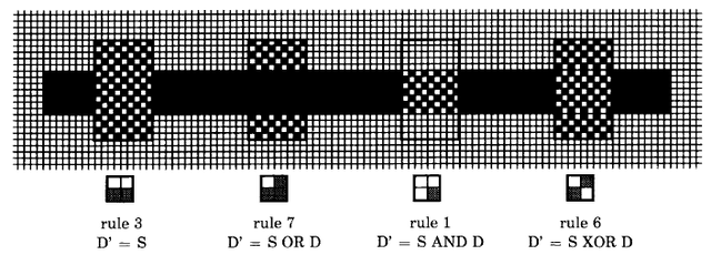
Figure 18.7 illustrates four common combination rules graphically. In addition, each is described by a combination diagram, its integer rule number, and the actual logical function being applied. The full set of 16 combination rules appears later in the chapter as part of the detailed simulation of BitBlt.
Classes Form and Bitmap
Figure 18.8 shows further information about the Form shown in Figure 18.2. The width and height are stored as Integers. The actual pixels are stored in a separate object which is an instance of class Bitmap. Bitmaps have almost no protocol, since their sole purpose is to provide storage for Forms. They also have no intrinsic width and height, apart from that laid on by their owning Form, although the figure retains this structure for clarity. It can be seen that space has been provided in the Bitmap for a width of 16; this is a manifestation of the hardware organization of storage and processing into 16-bit words. Bitmaps are allocated with an integral number of words for each row of pixels. This row size is referred to as the raster size. The integral word constraint on raster size facilitates movement from one row to the next within the operation of BitBlt, and during the scanning of the display screen by the hardware. While this division of memory into words is significant at the primitive level, it is encapsulated in such a way that none of the higher-level graphical components in the system need consider the issue of word size.
Two classes, Rectangle and Point, are used extensively in working with stored images. A Point contains x and y coordinate values and is used to refer to a pixel location in a Form; a Rectangle contains two Points--the top left corner and the bottom right corner--and is used to define a rectangular area of a Form.
Class Form includes protocol for managing a rectangular pattern of black and white dots. The bitmap of a Form can be (re)set by copying bits from a rectangular area of the display screen (fromDisplay:), and the extent and offset of the Form can be set (extent:, extent:offset:). Two messages provide access to the individual bits (valueAt: and valueAt:put:). Constants for modes and masks are known to class Form and can be obtained by the following class messages of Form.
| initialize-release | |
| fromDisplay: aRectangle | Copy the bits from the display screen within the boundaries defined by the argument, aRectangle, into the receiver's bitmap. |
| accessing | |
| extent: aPoint | Set the width and height of the receiver to be the coordinates of the argument, aPoint. |
| extent: extentPoint offset: offsetPoint | Set the width and height of the receiver to be the coordinates of the argument, extentPoint, and the offset to be offsetPoint. |
| pattern | |
| valueAt: aPoint | Answer the bit, 0 or 1, at location aPoint within the receiver's bitmap. |
| valueAt: aPoint put: bitCode | Set the bit at location aPoint within the receiver's bitmap to be bitCode, either 0 or 1. |
| Form instance protocol | |
| instance creation | |
| fromDisplay: aRectangle | Answer a new Form whose bits are copied from the display screen within the boundaries defined by the argument, aRectangle, into the receiver's bitmap. |
| mode constants | |
| erase | Answer the Integer denoting mode erase. |
| over | Answer the Integer denoting mode over. |
| reverse | Answer the Integer denoting mode reverse. |
| under | Answer the Integer denoting mode under. |
| mask constants | |
| black | Answer the Form denoting a black mask. |
| darkGray | Answer the Form denoting a dark gray mask. |
| gray | Answer the Form denoting a gray mask. |
| lightGray | Answer the Form denoting a light gray mask. |
| veryLightGray | Answer the Form denoting a very light gray mask. |
| white | Answer the Form denoting a white mask. |
| From class protocol | |
Spatial Reference
Since the images represented by Forms are inherently two-dimensional, image manipulation is simplified by providing objects representing two-dimensional locations and areas. Instances of class Point represent locations and instances of class Rectangle represent areas.
Class Point
A Point represents an x-y pair of numbers usually designating a pixel in a Form. Points refer to pixel locations relative to the top left corner of a Form (or other point of reference). By convention, x increases to the right and y down, consistent with the layout of text on a page and the direction of display scanning. This is in contrast to the "right-handed" coordinate system in which y increases in the upward direction.
A Point is typically created using the binary message @ to a Number. For example, the result of evaluating the expression
200 @ 150
is a Point with x and y coordinates 200 and 150. In addition, the class protocol of Point supports the instance creation message x: xInteger y: yInteger.
Point x: 200 y: 150
represents the same location as 200@150. The instance protocol for Point supports accessing messages and messages for comparing two Points.
| accessing | |
| x | Answer the x coordinate. |
| x: aNumber | Set the x coordinate to be the argument, aNumber. |
| y | Answer the y coordinate. |
| y: aNumber | Set the y coordinate to be the argument, aNumber. |
| comparing | |
| < aPoint | Answer whether the receiver is above and to the left of the argument, aPoint. |
| < = aPoint | Answer whether the receiver is neither below nor to the right of the argument, aPoint. |
| > aPoint | Answer whether the receiver is below and to the right of the argument, aPoint. |
| > = aPoint | Answer whether the receiver is neither above nor to the left of the argument, aPoint. |
| max: aPoint | Answer the lower right corner of the rectangle uniquely defined by the receiver and the argument, aPoint. |
| min: aPoint | Answer the upper left corner of the rectangle uniquely defined by the receiver and the argument, aPoint. |
| Point instance protocol | |
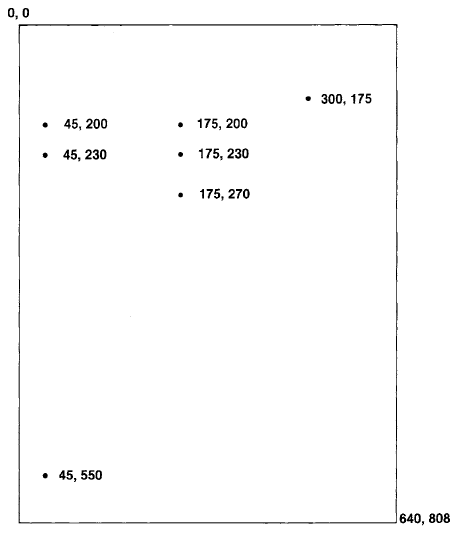
With respect to the coordinates labeled in Figure 18.9, example expressions are
| expression | result |
| (45@230) < (175@270) | true |
| (45@230) < (175@200) | false |
| (45@230) > (175@200) | false |
| (175@270) > (45@230) | true |
| (45@230) max: (175@200) | 175@230 |
| (45@230) min: (175@200) | 45@200 |
Arithmetic can be carried out between two Points or between a Point and a Number (a scaling factor). Each of the arithmetic messages takes either a Point or a Number (a scalar) as an argument, and returns a new Point as the result. Truncation and round off messages, similar to those for Numbers, are also provided in the instance protocol of Point.
| arithmetic | |
| * scale | Answer a new Point that is the product of the receiver and the argument, scale. |
| + delta | Answer a new Point that is the sum of the receiver and the argument, delta. |
| - delta | Answer a new Point that is the difference of the receiver and the argument, delta. |
| / scale | Answer a new Point that is the quotient of the receiver and the argument, scale. |
| // scale | Answer a new Point that is the quotient (defined by division with truncation toward negative infinity) of the receiver and the argument, scale. |
| abs | Answer a new Point whose x and y are the absolute values of the receiver's x and y. |
| truncation and round off | |
| rounded | Answer a new Point that is the receiver's x and y rounded. |
| truncateTo: grid | Answer a new Point that is the receiver's x and y truncated to the argument, grid. |
| Point instance protocol | |
Thus
| expression | result |
| (45@230) + (175@300) | 220@530 |
| (45@230) + 175 | 220@405 |
| (45@230) - (175@300) | -130@-70 |
| (160@240) / 50 | (16/5)@(24/5) |
| (160@240) // 50 | 3@4 |
| (160@240) // (50@50) | 3@4 |
| ((45@230) - (175@300)) abs | 130@70 |
| (120.5 @ 220.7) rounded | 121@221 |
| (160 @ 240) truncateTo: 50 | 150@200 |
Various other operations can be performed on Points including computing the distance between two Points, computing the dot product of two Points, transposing a point, and determining Points within some gridded range.
| point functions | |
| dist: aPoint | Answer the distance between the argument, aPoint, and the receiver. |
| dotProduct: aPoint | Answer a Number that is the dot product of the receiver and the argument, aPoint. |
| grid: aPoint | Answer a Point to the nearest rounded grid modules specified by the argument, aPoint. |
| normal | Answer a Point representing the unit vector rotated 90 deg clockwise. |
| transpose | Answer a Point whose x is the receiver's y and whose y is the receiver's x. |
| truncatedGrid: aPoint | Answer a Point to the nearest truncated grid modules specified by the argument, aPoint. |
| Point instance protocol | |
Examples are
| expression | result |
| (45@230) dist: 175@270 | 136.015 |
| (160@240) dotProduct: 50@50 | 20000 |
| (160@240) grid: 50@50 | 150@250 |
| (160@240) normal | -0.83105@0.5547 |
| (160@240) truncatedGrid: 50@50 | 150@200 |
| (175@300) transpose | 300@175 |
Points and Rectangles are used together as support for graphical manipulation. A Rectangle contains two Points--origin, which specifies the top left corner, and corner, which indicates the bottom right corner of the region described. Class Rectangle provides protocol for access to all the coordinates involved, and other operations such as intersection with other rectangles. Messages to a Point provide an infix way to create a Rectangle with the Point as the origin.
| converting | |
| corner: aPoint | Answer a Rectangle whose origin is the receiver and whose corner is the argument, aPoint. |
| extent: aPoint | Answer a Rectangle whose origin is the receiver and whose extent is the argument, aPoint. |
| Point instance protocol | |
Thus (45@200) corner: (175@270) represents the rectangular area shown earlier in the image of display coordinates.
Class Rectangle
Instances of Rectangle represent rectangular areas of pixels. Arithmetic operations take points as arguments and carry out scaling and translating operations to create new Rectangles. Rectangle functions create new Rectangles by determining intersections of Rectangles with Rectangles.
In addition to the messages to Point by which Rectangles can be created, class protocol for Rectangle supports three messages for creating instances. These messages specify either the boundaries of the rectangular area, the origin and corner coordinates, or the origin and width and height of the area.
| instance creation | |
| left: leftNumber right: rightNumber top: topNumber bottom: bottomNumber | Answer a Rectangle whose left, right, top, and bottom coordinates are determined by the arguments. |
| origin: originPoint corner: cornerPoint | Answer a Rectangle whose top left and bottom right corners are determined by the arguments, originPoint and cornerPoint. |
| origin: originPoint extent: extentPoint | Answer a Rectangle whose top left corner is originPoint and width by height is extentPoint. |
| Rectangle class protocol | |
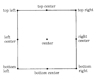
The accessing protocol for Rectangle is quite extensive. It supports detailed ways of referencing eight significant locations on the boundary of the Rectangle. These points are shown in Figure 18.10.
Messages for accessing these positions have selectors with names like those shown in the diagram.
| accessing | |
| topLeft | Answer the Point at the top left corner of the receiver. |
| topCenter | Answer the Point at the center of the receiver's top horizontal line. |
| topRight | Answer the Point at the top right corner of the receiver. |
| rightCenter | Answer the Point at the center of the receiver's right vertical line. |
| bottomRight | Answer the Point at the bottom right corner of the receiver. |
| bottomCenter | Answer the Point at the center of the receiver's bottom horizontal line. |
| bottomLeft | Answer the Point at the bottom left corner of the receiver. |
| leftCenter | Answer the Point at the center of the receiver's left vertical line. |
| center | Answer the Point at the center of the receiver. |
| area | Answer the receiver's area, the product of width and height. |
| width | Answer the receiver's width. |
| height | Answer the receiver's height. |
| extent | Answer the Point receiver's width @ receiver's height. |
| top | Answer the position of the receiver's top horizontal line. |
| right | Answer the position of the receiver's right vertical line. |
| bottom | Answer the position of the receiver's bottom horizontal line. |
| left | Answer the position of the receiver's left vertical line. |
| origin | Answer the Point at the top left corner of the receiver. |
| corner | Answer the Point at the bottom right corner of the receiver. |
| Rectangle instance protocol | |
Suppose the Rectangle referred to as frame is created by the expression
frame ← Rectangle origin: 100@100 extent: 150@150
then
| expression | result |
| frame topLeft | 100@100 |
| frame top | 100 |
| frame rightCenter | 250@175 |
| frame bottom | 250 |
| frame center | 175@175 |
| frame extent | 150@150 |
| frame area | 22500 |
Each of the Rectangle's locations can be modified by an accessing message whose keyword is one of the positions named in Figure 18.10. In addition, the width and height can be set with the messages width: and height:, respectively. Two messages are listed below that are commonly used in the implementation of the system programming interface in order to reset the variables of a Rectangle.
| accessing | |
| origin: originPoint corner: cornerPoint | Set the points at the top left corner and the bottom right corner of the receiver. |
| origin: originPoint extent: extentPoint | Set the point at the top left corner of the receiver to be originPoint and set the width and height of the receiver to be extentPoint. |
| Rectangle instance protocol | |
Rectangle functions create new Rectangles and compute relationships between two Rectangles.
| rectangle functions | |
| amountToTranslateWithin: a Rectangle | Answer a Point, delta, such that the receiver, when moved by delta, will force the receiver to lie within the argument, aRectangle. |
| areasOutside: aRectangle | Answer a collection of Rectangles comprising the parts of the receiver which do not lie within the argument, aRectangle. |
| expandBy: delta | Answer a Rectangle that is outset from the receiver by delta, where delta is a Rectangle, Point, or scalar. |
| insetBy: delta | Answer a Rectangle that is inset from the receiver by delta, where delta is a Rectangle, Point, or scalar. |
| insetOriginBy: originDeltaPoint cornerBy: cornerDeltaPoint | Answer a Rectangle that is inset from the receiver by originDeltaPoint at the origin and cornerDeltaPoint at the corner. |
| intersect: aRectangle | Answer a Rectangle that is the area in which the receiver overlaps with the argument, aRectangle. |
| merge: aRectangle | Answer the smallest Rectangle that contains both the receiver and the argument, aRectangle. |
| Rectangle instance protocol | |
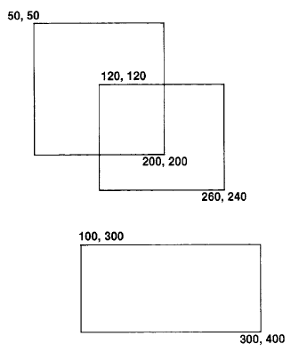
Figure 18.11 shows three Rectangles, A, B, and C, created as follows.
A ← 50@50 corner: 200@200.
B ← 120@120 corner: 260@240.
C ← 100@300 corner: 300@400
Then expressions using these three Rectangles are listed below. Notice that Rectangles print in the form originPoint corner: cornerPoint.
| expression | result |
| A amountToTranslateWithin: C | 50@250 |
| A areasOutside: B | OrderedCollection((50@50 corner: 200@120) (50@120 corner: 120@200)) |
| C expandBy: 10 | 90@290 corner: 310@410 |
| C insetBy: 10@20 | 110@320 corner: 290@380 |
| A intersect: B | 120@120 corner:200@200 |
| B merge: C | 100@120 corner: 300@400 |
The testing protocol for Rectangles includes messages to determine whether a Point or other Rectangle is contained within the boundaries of a Rectangle, or whether two Rectangles intersect.
| testing | |
| contains: aRectangle | Answer whether the receiver contains all Points contained by the argument, aRectangle. |
| containsPoint: aPoint | Answer whether the argument, aPoint, is within the receiver. |
| intersects: aRectangle | Answer whether the receiver contains any Point contained by the argument, aRectangle. |
| Rectangle instance protocol | |
Continuing the above example
| expression | result |
| A contains: B | false |
| C containsPoint: 200@320 | true |
| A intersects: B | true |
Like the messages for a Point, the coordinates of a Rectangle can be rounded to the nearest integer. A Rectangle can be moved by some amount, translated to a particular location, and the coordinates can be scaled or translated by some amount. Rectangles also respond to scaling and translating messages; they are part of the protocol for any object that can display itself on a display medium.
| truncation and round off | |
| rounded | Answer a Rectangle whose origin and corner coordinates are rounded to the nearest integer. |
| transforming | |
| moveBy: aPoint | Change the corner positions of the receiver so that its area translates by the amount defined by the argument, aPoint |
| moveTo: aPoint | Change the corners of the receiver so that its top left position is the argument, aPoint. |
| scaleBy: scale | Answer a Rectangle scaled by the argument, scale, where scale is either a Point or a scalar. |
| translateBy: factor | Answer a Rectangle translated by the argument, factor, where factor is either a Point or a scalar. |
| Rectangle instance protocol | |
For example
| expression | result |
| A moveBy: 50@50 | 100@100 corner: 250@250 |
| A moveTo: 200@300 | 200@300 corner: 350@450 |
| A scaleBy: 2 | 400@600 corner: 700@900 |
| A translateBy: -100 | 100@200 corner: 250@350 |
Class BitBlt
The most basic interface to BitBlt is through a class of the same name. Each instance of BitBlt contains the variables necessary to specify a BitBlt operation. A specific application of BitBlt is governed by a list of parameters, which includes:
| destForm | (destination form) a Form into which pixels will be stored |
| sourceForm | a Form from which pixels will be copied |
| halftoneForm | a Form containing a spatial halftone pattern |
| combinationRule | an Integer specifying the rule for combining corresponding pixels of the sourceForm and destForm |
| destX, destY, width, height | (destination area x, y, width, and height) Integers which specify the rectangular subregion to be filled in the destination |
clipX, clipY,
|
(clipping rectangular area x, y, width, and height) Integers which specify a rectangular area which restricts the affected region of the destination |
| sourceX, sourceY | Integers which specify the location (top left corner) of the subregion to be copied from the source |
The BitBlt class protocol consists of one message for creating instances; this message contains a keyword and argument for each BitBlt variable. The BitBlt instance protocol includes messages for initializing the variables and a message, copyBits, which causes the primitive operation to take place. It also contains a message, drawFrom: startPoint to: stopPoint, for drawing a line defined by two Points.
Biblt class protocol
instance creationg
destForm: destination
    sourceForm: source
    halftoneForm: halftone
    combinationRule: rule
    destOrigin: destOrigin
    sourceOrigin: sourceOrigin
    extent: extent
    clipRect: clipRect
|
Answer a Bitblt with values set according to each of the arguments, where rule is an Integer; destination, source, and halftone are Forms; destOrigin, sourceOrigin, and extent are Points; and clipRect is a Rectangle. |
| accessing | |
| sourceForm: aForm | Set the receiver's source form to be the argument, aForm. |
| destForm: aForm | Set the receiver's destination form to be the argument, aForm. |
| mask: aForm | Set the receiver's halftone mask form to be the argument, aForm. |
| combinationRule: anInteger | Set the receiver's combination rule to be the argument, anInteger, which must be an integer between 0 and 15. |
| clipHeight: anInteger | Set the receiver's clipping area height to be the argument, anInteger. |
| clipWidth: anInteger | Set the receiver's clipping area width to be the argument, anInteger. |
| clipRect | Answer the receiver's clipping rectangle. |
| clipRect: aRectangle | Set the receiver's clipping rectangle to be the argument, aRectangle. |
| clipX: anInteger | Set the receiver's clipping rectangle top left x coordinate to be the argument, anInteger. |
| clipY: anInteger | Set the receiver's clipping rectangle top left y coordinate to be the argument, anInteger. |
| sourceRect: aRectangle | Set the receiver's source form rectangular area to be the argument, aRectangle. |
| sourceOrigin: aPoint | Set the receiver's source form top left coordinates to be the argument, aPoint. |
| sourceX: anInteger | Set the receiver's source form top left x coordinate to be the argument, anInteger. |
| sourceY: anInteger | Set the receiver's source form top left y coordinate to be the argument, anInteger. |
| destRect: aRectangle | Set the receiver's destination form rectangular area to be the argument, aRectangle. |
| destOrigin: aPoint | Set the receiver's destination form top left coordinates to be the argument, aPoint. |
| destX: anInteger | Set the receiver's destination form top left x coordinate to be the argument, anInteger. |
| destY: anInteger | Set the receiver's destination form top left y coordinate to be the argument, anInteger. |
| height: anInteger | Set the receiver's destination form height to be the argument, anInteger. |
| width: anInteger | Set the receiver's destination form width to be the argument, anInteger. |
| copying | |
| copyBits | Perform the movement of bits from the source form to the destination form. Report an error if any variables are not of the right type (Integer or Form), or if the combination rule is not between 0 and 15 inclusive. Try to reset the variables and try again. |
| Bitblt instance protocol | |
The state held in an instance of BitBlt allows multiple operations in a related context to be performed without the need to repeat all the initialization. For example, when displaying a scene in a display window, the destination form and clipping rectangle will not change from one operation to the next. Thus the instance protocol for modifying individual variables can be used to gain efficiency.
Line Drawing
Much of the graphics in the Smalltalk-80 system consists of lines and text. These entities are synthesized by repeated invocation of BitBlt.
The BitBit protocol includes the messages drawFrom: startPoint to: stopPoint to draw a line whose end points are the arguments, startPoint and stopPoint.
| line drawing | |
| drawFrom: startPoint to: stopPoint | Draw a line whose end points are the arguments, startPoint and stopPoint. The line is formed by displaying copies of the current source form according to the receiver's halftone mask and combination rule. |
| Bitblt instance protocol | |
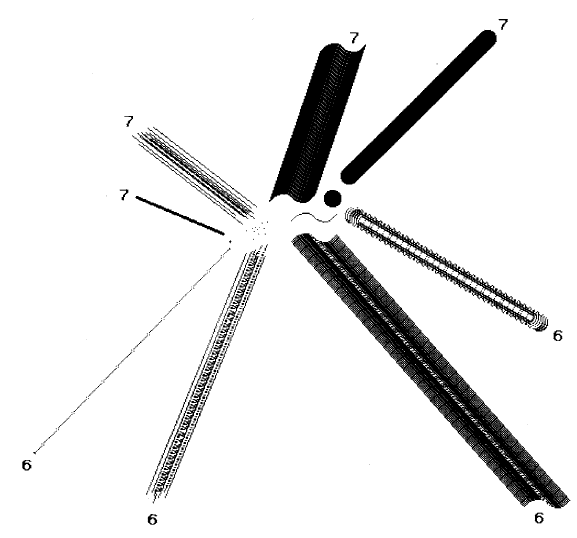
By using BitBlt, one algorithm can draw lines of varying widths, different halftones, and any combination rule. To draw a line, an instance of BitBlt is initialized with the appropriate destination Form and clipping rectangle, and with a source that can be any Form to be applied as a pen or "brush" shape along the line. The message drawFrom:to: with Points as the two arguments is then sent to the instance. Figure 18.12 shows a number of different pen shapes and the lines they form when the BitBlt combination rule is 6 or 7.
The message drawFrom: startPoint to: stopPoint stores the destX and destY values. Starting from these stored values, the line-drawing loop, drawLoopX: xDeita Y: yDeita, shown next, accepts x and y delta values and calculates x and y step values to determine points along the line, and then calls copyBits in order to display the appropriate image at each point. The method used is the Bresenham plotting algorithm (IBM Systems Journal, Volume 4, Number 1, 1965). It chooses a principal direction and maintains a variable, p When p's sign changes, it is time
to move in the minor direction as well. This method is a natural unit to be implemented as a primitive method, since the computation is trivial and the setup in copyBits is almost all constant from one invocation to the next.
The method for drawLoopX: xDelta Y: yDelta in class BitBlt is
drawLoopX: xDelta Y: yDelta
    | dx dy px py p |
    dx ← xDelta sign.
    dy ← yDelta sign.
    px ← yDelta abs.
    py ← xDelta abs.
    self copyBits. "first point"
    py > px
        ifTure: "more horizontal"
            [p ← py // 2.
                1 to: py do:
                    [ :i | destx ← destx + dx.
                        (p ← p - px) < 0
                            ifTrue: [desty ← desty + dy. p ← p + py].
                        self copyBits]]
        ifFalse: "more vertical"
            [p ← px//2.
                1 to: px do:
                    [ :i | desty ← desty + dy.
                        (p ← p - py) < 0
                            ifTrue: [destx ← destx + dx. p ← p + px].
                        self copyBits]]
Text Display
One of the advantages derived from BitBlt is the ability to store fonts compactly and to display them using various combination rules. The compact storage arises from the possibility of packing characters horizontally one next to another (as shown earlier in Figure 18.3), since BitBlt can extract the relevant bits if supplied with a table of left x coordinates of all the characters. This is called a strike format from the typographical term meaning a contiguous display of all the characters in a font.
The scanning and display of text are performed in the Smalltalk-80 system by a subclass of BitBlt referred to as CharacterScanner. This subclass inherits all the normal state, with destForm indicating the Form in which text is to be displayed and sourceForm indicating a Form containing all the character glyphs side by side (as in Figure 18.3). In addition CharacterScanner defines further state including:
| text | a String of Characters to be displayed |
| textPos | an Integer giving the current position in text |
| xTable | an Array of Integers giving the left x location of each character in sourceForm |
| stopX | an Integer that sets a right boundary past which the inner loop should stop scanning |
| exceptions | an Array of Symbols that, if non-nil, indicate message for handling the corresponding characters specially |
| printing | a Boolean indicating whether characters are to be printed |
Once an instance has been initialized with a given font and text location, the scanWord: loop below will scan or print text until some horizontal position (stopX) is passed, until a special character (determined from exceptions) is found, or until the end of this range of text (endRun) is reached. Each of these conditions is denoted by a symbolic code referred to as stopXCode, exceptions (an Array of Symbols) and endRunCode.
scanword: endRun
    | charIndex |
    [textPos < endRun] whileTrue:
        ["pick character" charIndex ← text at: textPos.
            "check exceptions"
            (exceptions at: charIndex) > 0
                ifTrue: [↑exceptions at: charIndex].
            "left x of character in font" sourceX ← xTable at: charIndex.
            "up to left of next char"
            width ← (xTable at: charIndex + 1) - sourceX.
            "print the character" printing ifTrue: [self copyBits].
            "advance by width of character" destX ← destX + width.
            destX > stopX ifTrue: [↑stopXCode]. "passed right boundary"
            "advance to next character"
            textPos ← textPos + 1].
        textPos ← textPos - 1.
        ↑endRunCode
The check on exceptions handles many possibilities in one operation. The space character may have to be handled exceptionally in the case of text that is padded to achieve a flush right margin. Tabs usually require a computation or table lookup to determine their width. Carriage return is also identified in the check for exceptions. Character codes beyond the range given in the font are detected similarly, and are usually handled by showing an exceptional character, such as a little lightning bolt, so that they can be seen and corrected.
The printing flag can be set false to allow the same code to measure a line (break at a word boundary) or to find to which character the cursor points. While this provision may seem over-general, two benefits (besides compactness) are derived from that generality. First, if one makes a change to the basic scanning algorithm, the parallel functions of measuring, printing, and cursor tracking are synchronized by definition. Second, if a primitive implementation is provided for the loop, it exerts a threefold leverage on the system performance.
The scanword: loop is designed to be amenable to such primitive implementation; that is, the interpreter may intercept it and execute primitive code instead of the Smalltalk-80 code shown. In this way, much of the setup overhead for copyBits can be avoided at each character and an entire word or more can be displayed directly. Conversely, the Smalltalk text and graphics system requires implementation of only the one primitive operation (BitBlt)to provide full functionality.
Simulation of Bitblt
We provide here a simulation of an implementation of copyBits in a subclass of BitBlt referred to as BitBltSimulation. The methods in this simulation are intentionally written in the style of machine code in order to serve as a guide to implementors. No attempt is made to hide the choice of 16-bit word size. Although the copyBits method is presented as a Smalltalk-80 method in BitBltSimulation, it is actually implemented in machine-code as a primitive method in class BitBlt; the simulation does the same thing, albeit slower.
| class name | BitbltSimulation |
| superclass | Bitblt |
| instance variable names | sourceBits sourceRaster destBits destRaster halftoneBits skew skewMask mask1 mask2 preload nWords hDir vDir sourceIndex sourceDelta destIndex destDelta sx sy dx dy w h |
| class variable names | AllOnes RightMasks |
| class methods | initialize
"Initialize a table of bit masks"
RightMasks ←
#(0 16r1 16r3 16r7 16rF
16r1F 16r3F 16r7F 16rFF
16r1FF 16r3FF 16r7FF 16rFFF
16r1FFF 16r3FFF 16r7FFF 16rFFFF).
AllOnes ← 16rFFFF
|
| instance methods | operations
copyBits
"sets w and h"
self clipRange.
(w < = or: [h < = 0]) ifTrue: [↑self]. "null range"
self computeMasks.
self checkOverlap.
self calculateOffsets.
self copyLoop
private
clipRange
"clip and adjust source origin and extent appropriately"
"first in x"
destX > = clipX
ifTrue: [sx ← sourceX. dx ← destX. w ← width]
ifFalse: [sx ← sourceX + (clipX - destX).
w ← width - (clipX - destX).
dx ← clipX].
(dx + w) > (clipX + clipWidth)
ifTrue: [w ← w - ((dx + w) - (clipX + clipWidth))].
"then in y"
destY > = clipY
ifTrue: [sy ← sourceY. dy ← destY. h ← height]
ifFalse: [sy ← sourceY + clipY - destY.
h ← height - clipY + destY.
dy ← clipY].
(dy + h) > (clipY + clipHeight)
ifTrue: [h ← h - ((dy + h) - (clipY + clipHeight))].
sx < 0
ifTrue: [dx ← dx - sx. w ← w + sx. sx ← 0].
sx + w > sourceForm width
ifTrue: [w ← w - (sx + w - sourceForm width)].
sy < 0
ifTrue: [dy ← dy - sy. h ← h + sy. sy ← 0].
sy + h > sourceForm height
ifTrue: [h ← h - (sy + h - sourceForm height)]
|
Clipping first checks whether the destination x lies to the left of the clipping rectangle and, if so, adjusts both destination x and width. As mentioned previously, the data to be copied into this adjusted rectangle comes from a shifted region of the source, so that the source x must also be adjusted. Next, the rightmost destination x is compared to the clipping rectangle and the width is decreased again if necessary. This whole process is then repeated for y and height. Then the height and width are clipped to the size of the source form. The adjusted parameters are stored in variables sx, sy, dx, dy, w, and h. If either width or height is reduced to zero, the entire call to BitBlt can return immediately.
ComputeMasks
    | startBits endBits |
    "calculate skew and edge masks"
    distBits ← destForm bits.
    destRaster ← destForm width - 1 // 16 + 1.
    sourceForm notNil
        ifTrue: [sourceBits ← sourceForm bits.
            sourceRaster ← sourceForm width - 1 // 16 + 1].
    halftoneForm notNil
        ifTrue: [halftoneBits ← halftoneForm bits].
    skew ← (sx - dx) bitAnd: 15.
    "how many bits source gets skewed to right"
    startBits ← 16 - (dx bitAnd: 15).
    "how many bits in first word"
    mask1 ← RightMasks at: startBits + 1.
    endBits ← 15 - ((dx + w - 1) bitAnd: 15).
    "how many bits in last word"
    mask2 ← (RightMasks at: endBits + 1) bitInvert.
    skewMask ←
        (skew = 0
            ifTrue: [0]
            ifFalse: [RightMasks at: 16 - skew + 1]).
    "determine number of words stored per line; merge masks if necessary"
    w < startBits
        ifTrue: [mask1 ← mask1 bitAnd: mask2.
            mask2 ← 0.
            nWords ← 1]
        ifFalse: [nWords ← (w - startBits - 1) // 16 + 2].
In preparation for the actual transfer of data, several parameters are computed. First is skew, the horizontal offset of data from source to destination. This represents the number of bits by which the data will have.to be rotated after being loaded from the source in order to line up with the final position in the destination. In the example of Figure 18.3, skew would be 5 because the glyph for the character "e" must be shifted left by 5 bits prior to being stored into the destination. From skew, skewMask is saved for use in rotating (this is unnecessary for machines with a rotate word instruction). Then mask1 and mask2 are computed for selecting the bits of the first and last partial words of each scan line in the destination. These masks would be 16r1FFF and 16rFFC0 respectively in the example of Figure 18.3 since startBits= 13 and endBits=6. In cases such as this where only one word of each destination line is affected, the masks are merged to select the range within that word, here 16r1FC0.
checkOverlap
    | t |
    "check for possible overlap of source and destination"
    hDir ← vDir ← 1. "defaults for no overlap"
    (sourceForm = = destForm and: [dy > = sy])
        ifTrue:
            [dy > sy "have to start at bottom"
                ifTrue: [vDir ← - 1. sy ← sy + h - 1. dy ← dy + h - 1]
                ifFalse: [dx > sx "y's are equal, but x's are backward"
                    ifTrue: [hDir ← -1.
                        sx ← sx + w - 1.
                        "start at right"
                        dx ← dx + w - 1.
                        "and fix up masks"
                        skewMask ← skewMask bitInvert.
                        t ← mask1.
                        mask1 ← mask2.
                        mask2 ← t]]]
A check must be made for overlapping source and destination. When source and destination lie in the same bitmap, there is the possibility of the copy operation destroying the data as it is moved. Thus when the data is being moved downward, the copy must start at the bottom and proceed upward. Similarly when there is no vertical movement, if the horizontal movement is to the right, the copy must start at the right and work back to the left. In all other cases the copy can proceed from top to bottom and left to right.
calculateOffsets
    "check if need to preload buffer
    (i.e., two words of source needed for first word of destination)"
    preload ← (sourceForm notNil) and:
        [skew ,~= 0 and: [skew < = (sx bitAnd: 15)]].
    hDir < 0 ifTrue: [preload ← preload == false].
    " calculate starting offsets"
    sourceIndex ← sy * sourceRaster + (sx// 16).
    destIndex ← dy * destRaster + (dx// 16).
    " calculate increments from end of 1 line to start of next"
    sourceDelta ←
        (sourceRaster * vDir) -
            (nWords + (preload ifTrue: [1] ifFalse: [0]) * hDir).
    destDelta ← (destRaster * vDir) - (nWords * hDir)
In cases where two words of source are needed to store the first word into the destination, a flag preload is set indicating the need to preload a 32-bit shifter prior to the inner loop of the copy (this is an optimization; one could simply always load an extra word initially). The offsets needed for the inner loop are the starting offset in words from the source and destination bases; deltas are also computed for jumping from the end of the data in one scanline to the start of data in the next.
inner loop
    copyLoop
        I prevWord thisWord skewWord mergeMask
            halftoneWord mergeWord word |
        1 to: h do: " here is the vertical loop:"
                [:i |
                    (halftoneForm notNil)
                        ifTrue:
                            [halftoneWord ← halftoneBits at: (1 + (dy bitAnd: 15)).
                                dy ← dy + vDir]
                        ifFalse: [halftoneWord ← AllOnes].
                    skewWord ← halftoneWord.
    preload
        ifTrue: [prevWord ← sourceBits at: sourceIndex + 1.
            "load the 32-bit shifter"
            sourceIndex ← sourceIndex + hDir]
        ifFalse: [prevWord ← 0].
    mergeMask ← mask1.
    1 to to: nWords do: "here is the inner horizontal loop"
        [ :word |
            sourceForm notNil " if source is used"
                ifTrue:
                    [prevWord ← prevWord bitAnd: skewMask.
                    thisWord ← sourceBits at: sourceIndex + 1.
                                "pick up next word"
                    skewWord ←
                        prevWord bitOr: (this Word bitAnd: skewMask bitInvert).
                    prevWord ← thisWord.
                    skewWord ← (skewWord bitShift: skew) bitOr:
                            (skewWord bitShift: skew - 16)]. "
                                "16-bit rotate"
            mergeWord ← self merge: (skewWord bitAnd: halftoneWord)
                            with: (destBits at: destIndex + 1).
            destBits
                at: destIndex + 1
                put: ((mergeMask bitAnd: mergeWord)
                        bitOr: (mergeMask bitInvert
                            bitAnd: (destBits at: destIndex + 1))).
            sourceIndex ← sourceIndex + hDir.
            destIndex ← destIndex + hDir.
            word = (nWords - 1)
                ifTrue: [mergeMask ← mask2]
                ifFalse: [mergeMask ← AllOnes]].
        sourceIndex ← sourceIndex + sourceDelta.
        destIndex ← destIndex + destDelta]
The outer, or vertical, loop includes the overhead for each line, selecting the appropriate line of halftone gray, preloading the shifter if necessary, and stepping source and destination pointers to the next scanline after the inner loop. It should be noted here that the reason for indexing the halftone pattern by the destination y is to eliminate "seams" which would occur if the halftones in all operations were not coordinated this way.
The inner, or horizontal, loop picks up a new word of source, rotates it with the previous, and merges the result with a word of the destination. The store into the destination must be masked for the first and last partial words on each scanline, but in the middle, no masking is really necessary.
merge: sourceWord with: destinationWord
    "These are the 16 combination rules:"
    combinationRule = 0
        ifTrue: [↑O].
    combinationRule = 1
        ifTrue: [↑sourceWord bitAnd: destinationWord].
    combinationRule = 2
        ifTrue: [↑sourceWold bitAnd: destinationWord bitInvert].
    combinationRule= 3
        ifTrue: [↑sourceWord].
    combinationRule= 4
        ifTrue: [↑sourceWord bitInvert bitAnd: destinationWord].
    combinationRule = 5
        ifTrue: [↑destinationWord].
    combinationRule =6
        ifTrue:[↑sourceWord bitXor: destinationWord].
    combinationRule= 7
        ifTrue: [↑sourceWord bitOr: destinationWord].
    combinationRule = 8
        ifTrue: [↑sourceWord bitInvert bitAnd: destinationWord bitInvert].
    combinationRule = 9
        ifTrue: [↑sourceWord bitInvert bitXor: destinationWord].
    combinationRule = 10
        ifTrue: [↑destinationWord bitInvert].
    combinationRule = 11
        ifTrue: [↑sourceWord bitOr: destinationWord bitInvert].
    combinationRule = 12
        ifTrue: [↑sourceWord bitInvert].
    combinationRule= 13
        ifTrue: [↑sourceWord bitInvert bitOr: destinationWord].
    combinationRule= 14
        ifTrue: [↑sourceWord bitInvert bitOr: destinationWord bitInvert].
    combinationRule = 15
        ifTrue: [↑AllOnes]
Efficiency Considerations
Our experience has demonstrated the value of BitBlt's generality. This one primitive is so central to the programming interface that any improvement in its performance has considerable effect on the interactive quality of the system as a whole. In normal use of the Smalltalk-80 system, most invocations of BitBlt are either in the extreme microscopic or macroscopic range.
In the macroscopic range, the width of transfer spans many words. The inner loop across a horizontal scan line gets executed many times, and the operations requested tend to be simple moves or constant stores. Examples of these are:
- clearing a line of text to white
- clearing an entire window to white
- scrolling a block of text up or down
Most processors provide a fast means for block moves and stores, and these can be made to serve the applications above. Suppose we structure the horizontal loop of BitBlt as
- move left partial word,
- move many whole words (or none),
- move right partial word (or none).
Special cases can be provided for 2 if the operation is a simple store or a simple copy with no skew (horizontal bit offset) from source to destination. In this way, most macroscopic applications of BitBit can be made fast, even on processors of modest power.
The microscopic range of BitBlt is characterized by a zero count for the inner loop. The work on each scanline involves at most two partial words, and both overall setup and vertical loop overhead can be considerably reduced for these cases. Because characters tend to be less than a word wide and lines tend to be less than a word thick, nearly all text and line drawing falls into this category. A convenient way to provide such efficiency is to write a special case of BitBlt which assumes the microscopic parameters, but goes to the general BitBlt whenever these are not met. Because of the statistics (many small operations and a few very large ones), it does not hurt to pay the penalty of a false assumption on infrequent calls. One can play the same trick with clipping by assuming no clipping will occur and running the general code only when this assumption fails.
