Smalltalk80LanguageImplementation:Chapter 20
- Chapter 20 Display Objects
Display Objects
Object

    Magnitude
        Character
        Date
        Time

        Number
            Float
            Fraction
            Integer
                LargeNegativeInteger
                LargePositiveInteger
                SmallInteger

        LookupKey
            Association

    Link

        Process

    Collection

        SequenceableCollection
            LinkedList

                Semaphore

            ArrayedCollection
                Array

                Bitmap
                    DisplayBitmap

                RunArray
                String
                    Symbol
                Text
                ByteArray

            Interval
            OrderedCollection
                SortedCollection
        Bag
        MappedCollection
        Set
            Dictionary
                IdentifyDictionary

    Stream
        PositionableStream
            ReadStream
            WriteStream
                ReadWriteStream
                    ExternalStream
                        FileStream

        Random

    File
    FileDirectory
    FilePage

    UndefinedObject
    Boolean
        False
        True

    ProcessorScheduler
    Delay
    SharedQueue

    Behavior
        ClassDescription
            Class
            MetaClass

    Point
    Rectangle
    BitBit
        CharacterScanner

        Pen

    DisplayObject***
        DisplayMedium***
            Form***
                Cursor***
                DisplayScreen***
        InfiniteForm***
        OpaqueForm***
        Path***
            Arc***
                Circle***
            Curve***
            Line***
            LinearFit***
            Spline***
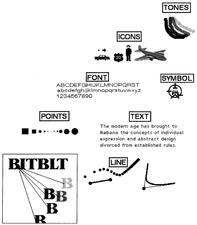
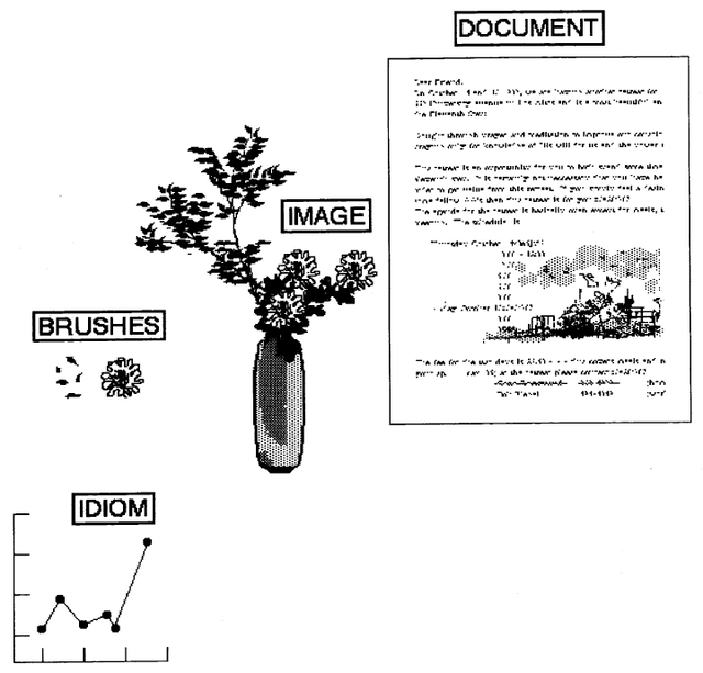
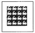
Graphics in the Smalltalk-80 system begin with the specification of BitBlt. Supported by Points, Rectangles, Forms, Pens, and Text, a wide variety of imagery can be created. The images in Figure 20.1 illustrate some of the graphical entities made possible by extending the use of these five kinds of objects.
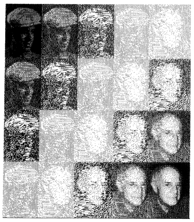
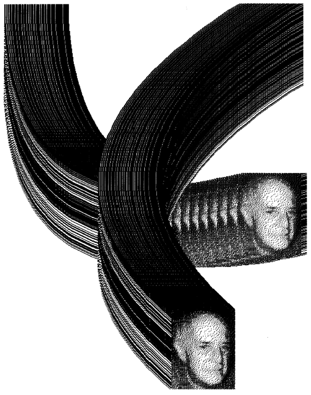
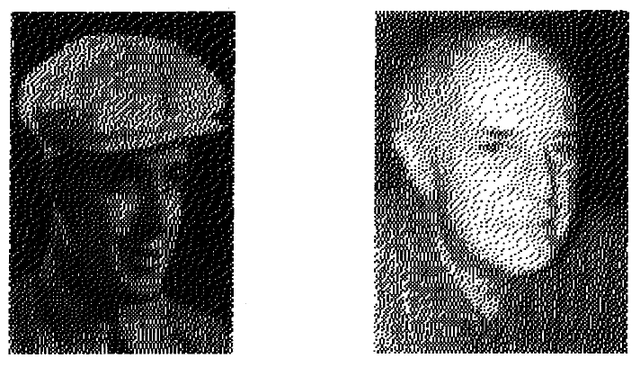
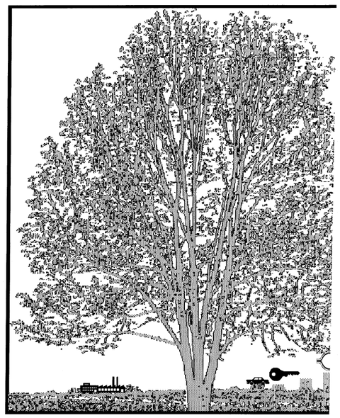
The more artistic images in Figures 20.2 and 20.3 were created using the additional display objects available in the Smalltalk-80 system. The methods used in creating these images are described later. This chapter describes the available kinds of display objects and the various ways to manipulate them.
Class DisplayObject
A Form is a kind of display object. There are others in the system. The way in which these objects are implemented is as a hierarchy of classes whose superclass is named DisplayObject. Form is a subclass in this hierarchy.
A display object represents an image that has a width, a height, an assumed origin at 0@0, and an offset from this origin relative to which the image is to be displayed. All display objects are similar in their ability to copy their image into another image, to be scaled, and to be translated. They differ in how their image is created.
There are three primary subclasses of DisplayObject. They are DisplayMedium, DisplayText, and Path.
- DisplayMedium represents images that can be "colored" (that is, filled with a gray tone) and bordered (that is, their rectangular outline is colored).
- DisplayText represents textual images.
- Path represents images composed as collections of images.
A Form is a subclass of DisplayMedium; it adds the bitmap representation of the image. All DisplayObjects provide source information for images; Forms provide both the source and the destination information.
Class DisplayObject supports accessing messages for manipulating the various aspects of the image.
| accessing | |
| width | Answer the width of the receiver's bounding box, a rectangle that represents the boundaries of the receiver's image. |
| height | Answer the height of the receiver's bounding box. |
| extent | Answer a Point representing the width and height of the receiver's bounding box. |
| offset | Answer a Point representing the amount by which the receiver should be offset when it is displayed or its position is tested. |
| offset: aPoint | Set the receiver's offset. |
| rounded | Set the receiver's offset to the nearest integral amount. |
| DisplayObject instance protocol | |
DisplayObject also provides three kinds of messages that support transforming an image, displaying the image, and computing the display box, that is, a rectangular area that represents the boundaries of the area for displaying the image.
| transforming | |
| scaleBy: aPoint | Scale the receiver's offset by aPoint. |
| translateBy: aPoint | Translate the receiver's offset by aPoint. |
| align: alignmentPoint with: relativePoint | Translate the receiver's offset such that alignmentPoint aligns with relativePoint. |
| display box access | |
| boundingBox | Answer the rectangular area that represents the boundaries of the receiver's space of information. |
| displaying | |
displayOn: aDisplayMedium
    at: aDisplayPoint
    clippingBox: clipRectangle
    rule: ruleInteger
    mask: aForm||
|
Display the receiver at location aDisplayPoint with rule, ruleInteger, and halftone mask, aForm. Information to be displayed must be confined to the area that intersects with clipRectangle. |
| DisplayObject instance protocol | |
There are actually several displaying messages not shown above. Alternative displaying messages progressively omit a keyword (starting from the last one) and provide default masks, rules, clipping rectangles, and positions, when needed. Basically the display screen itself is the default clipping rectangle, 0@0 is the default display position, and the object that represents the system display screen, Display, (a global variable) is the default display medium.
The message displayAt: aDisplayPoint provides a generally useful message when the only parameter not defaulted is the location at which the image is to be placed. The message display assumes that the display location is 0@0.
| displayAt: aDisplayPoint | Display the receiver at location aDisplayPoint with rule "over" or "storing"; halftone mask, a black Form; clipping rectangle the whose display screen; onto the display screen (Display). |
| display | Display the receiver at location 0@0. |
| DisplayObject instance protocol | |
These last two displaying messages are provided for textual objects such as String and Text as well, so that the programmer can place characters on the screen by evaluating an expression such as
'This is text to be displayed' displayAt: 100@100
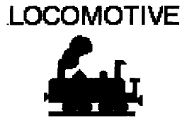
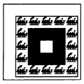
Suppose locomotive is the Form that looks like
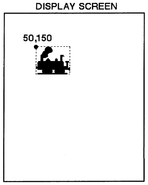
then it can be displayed on the screen with top left cornet at location 50@150 by evaluating the expression
locomotive displayAt: 50@150
Class DisplayMedium
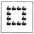
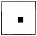
DisplayMedium is a subclass of DisplayObject that represents an object onto which images can be copied. In addition to those messages inherited from its superclass, DisplayMedium provides protocol for coloring the interior of images and placing borders around the display boxes of images. The "colors" are Forms that are already available in the system. These are black (the bitmap is all ones), white (all zeros), and various gray tones, either gray, veryLightGray, lightGray, or darkGray (mixtures of ones and zeros). Images of these colors are given below. All or portions of the DisplayMedium's area can be changed to one of these colors using the following messages.
| coloring | |
| black | Change all of the receiver's area to black. |
| black: aRectangle | Change the area of the receiver defined by the argument, aRectangle, to black. |
| white | Change all of the receiver's area to white. |
| white: aRectangle | Change the area of the receiver defined by the argument, aRectangle, to white. |
| gray | Change all of the receiver's area to gray. |
| gray: aRectangle | Change the area of the receiver defined by the argument, aRectangle, to gray. |
| veryLightGray | Change all of the receiver's area to very light gray. |
| veryLightGray: aRectangle | Change the area of the receiver defined by the argument, aRectangle, to very light gray. |
| lightGray | Change all of the receiver's area to light gray. |
| lightGray: aRectangle | Change the area of the receiver defined by the argument, aRectangle, to light gray. |
| darkGray | Change all of the receiver's area to dark gray. |
| darkGray: aRectangle | Change the area of the receiver defined by the argument, aRectangle, to dark gray. |
| DisplayMedium instance protocol | |
In the above messages, the origin of the argument, aRectangle, is in the coordinate system of the receiver.
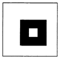
Suppose picture is a kind of DisplayMedium that is 100 pixels in width and 100 pixels in height, and that box is an instance of Rectangle with origin at 30 @ 30 and width and height of 40. Then the protocol for filling the subarea of picture represented by box is illustrated by the following sequence.
| expression | result |
| picture black: box | 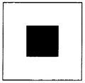
|
| picture white: box | 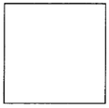
|
| picture gray: box | 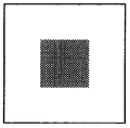
|
| picture lightGray: box | 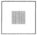
|
| picture veryLightGray:box | 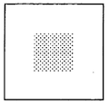
|
| picture darkGray: box | 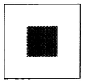
|
Part of an image can be filled with a pattern by sending a DisplayMedium a message to fill a particular sub-area with a halftone pattern. The other coloring messages use these filling messages in their implementation.
| fill: aRectangle mask: aHalftoneForm | Change the area of the receiver defined by the argument, aRectangle,to white, by filling it with the 16 x 16-bit pattern, aHalftoneForm. The combination rule for copying the mask to the receiver is 3 (Form over). |
| fill: aRectangle rule: anInteger mask: aHalftoneForm | Change the area of the receiver defined by the argument, aRectangle, to white, by filling it with the 16 x 16 bit pattern, aHalftoneForm. The combination rule for copying the mask to the receiver is anInteger. |
| DisplayMedium instance protocol | |
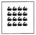
As an example, the result of evaluating the expressions
box ← 16@16 extent: 64@64.
picture fill: box mask: locomotive
where locomotive is a 16x16-bit Form, is
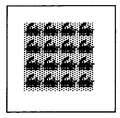
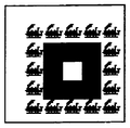
The result of evaluating the sequence of two expressions
picture lightGray: box.
picture fill: box rule: Form under mask: locomotive
is
Note that in the above, the rule Form under refers to an Integer combination rule. Messages to Form to access combination rules and halftone masks were defined in Chapter 18.
Reversing an image means changing all the bits in the area that are white to black and those that are black to white. Either all or part of an image can be reversed.
| reverse: aRectangle mask: aHalftoneForm | Change the area in the receiver defined by the argument, aRectangle, so that, in only those bits in which the mask, aHalftoneForm, is black, white bits in the receiver become black and black become white. |
| reverse: aRectangle | Change the area in the receiver defined by the argument, aRectangle, so that white is black and black is white. The default mask is Form black. |
| reverse | Change all of the receiver's area so that white is black and black is white. |
| DisplayMedium instance Protocol | |
The result of
picture reverse: box
on the last image is
Bordering means Coloring the outline of a rectangle. Bordering is done using a source Form and mask. Three messages provide methods for bordering an image.
| bordering | |
| border: aRectangle widthRectangle: insets mask: aHalftoneForm | Color an outline around the area within the receiver defined by the argument, aRectangle. The color is determined by the mask, aHalftoneForm. The width of the outline is determined by the Rectangle, insets, such that, origin x is the width of the left side, origin y is the width of the top side, corner x is the width of the right side, and corner y is the width of the bottom side. |
| border: aRectangle width: borderWidth mask: aHalftoneForm | Color an outline around the area within the receiver defined by the argument, aRectangle. The color is determined by the mask, aHalftoneForm. The width of all the sides is borderWidth. |
| border: aRectangle width: borderWidth | Color an outline around the area within the receiver defined by the argument, aRectangle. The color is Form black. The width of all the sides is borderWidth. |
| DisplayMedium instance protocol | |
Examples are
The next sequence of images shows how bordering can be done by manipulating the size of the rectangle used to designate which area within picture should be changed.
Forms
Class Form is the only subclass of DisplayMedium in the standard Smalltalk-80 system. It was introduced in Chapter 18 in which we defined messages that provide access to constants representing masks and combination rules (modes). As an illustration of the use of Forms in creating complex images, the following sequence of expressions creates the image shown at the beginning of this chapter as Figure 20.2.
Suppose we have two Forms available, each 120 bits wide and 180 bits high. We name them face25 and face75. These images were created using a scanner to digitize photographs of a gentleman when he was in his 20's and on the occasion of his 75th birthday.
The scanned images were scaled to the desired size and then combined with halftone masks in the following way. Two Arrays, each size 8, contain references to the halftone masks (masks) and the Forms (forms) used in creating each part of the final image.
masks ← Array new: 8.
masks at: 1 put: Form black.
masks at: 2 put: Form darkGray.
masks at: 3 put: Form gray.
masks at: 4 put: Form lightGray.
masks at: 5 put: Form veryLightGray.
masks at: 6 put: Form lightGray.
masks at: 7 put: Form gray.
masks at: 8 put: Form black.
forms ← Array new: 8.
forms at: 1 put: face25.
forms at: 2 put: face25.
forms at: 3 put: face25.
forms at: 4 put: face25.
forms at: 5 put: face75.
forms at: 6 put: face75.
forms at: 7 put: face75.
forms at: 8 put: face75
The variable i is the initial index into the first halftone and first Form used in forming the first sub-image of each row. Each time a complete row is displayed, i is incremented by 1. Each row consists of 5 elements. The variable index is used to index 5 halftones and five Forms; index is set to i at the outset of each row. Thus the first row is made up by combining elements 1, 2, 3, 4, and 5 of masks and forms; the second row is made up by combining elements 2, 3, 4, 5, and 6 of masks and forms; and so on. The y coordinate of each row changes by 180 pixels each time; the x coordinate of each column changes by 120 pixels.
i ← 1.
0 to: 540 by: 180 do:
    [ :y | index ←.
        0 to: 480 by: 120 do:
            [ :x | (forms at: index)
                displayOn: Display
                at: x@y
                clippingBox: Display boundingBox
                rule: Form over
                mask: (masks at: index).
            index ← index + 1].
        i ← i + 1]
Other Forms
Two other kinds of forms exist in the system, InfiniteForm and OpaqueForm. These two classes are subclasses of DisplayObject, rather than of DisplayMedium. They therefore do not share Form's inherited ability to be colored and bordered. InfiniteForm represents a Form obtained by replicating a pattern Form indefinitely in all directions. Typically the overlapping views displayed in the Smalltalk-80 programming interface (as shown in Chapter 17) are placed over a light gray background; this background is defined by an InfiniteForm whose replicated pattern is Form gray. OpaqueForms represent a shape as well as a figure Form. The shape indicates what part of the background should be occluded in displaying the image, so that patterns other than black in the figure will still appear opaque. Instances of OpaqueForm support creating animations. Neither InfiniteForm nor OpaqueForm adds new protocol.
Cursors
Form has two subclasses of interest, class Cursor and class DisplayScreen. The Smalltalk-80 system makes extensive use of Forms to indicate both the current location of the hardware pointing device and the current status of the system. A Form used in this way is referred to as a cursor since its primary purpose is to move over the screen in order to locate screen coordinates.
Instances of class Cursor are Forms that are 16 pixels wide and 16 pixels high. Class Cursor adds three new messages to the displaying protocol that it inherits from DisplayObject.
| displaying | |
| show | Make the receiver be the current cursor shape. |
| showGridded: gridPoint | Make the receiver be the current cursor shape, forcing the location of cursor to the point nearest the location, gridPoint. |
| showWhile: aBlock | While evaluating the argument, aBlock, make the receiver be the cursor shape. |
| Cursor instance protocol | |
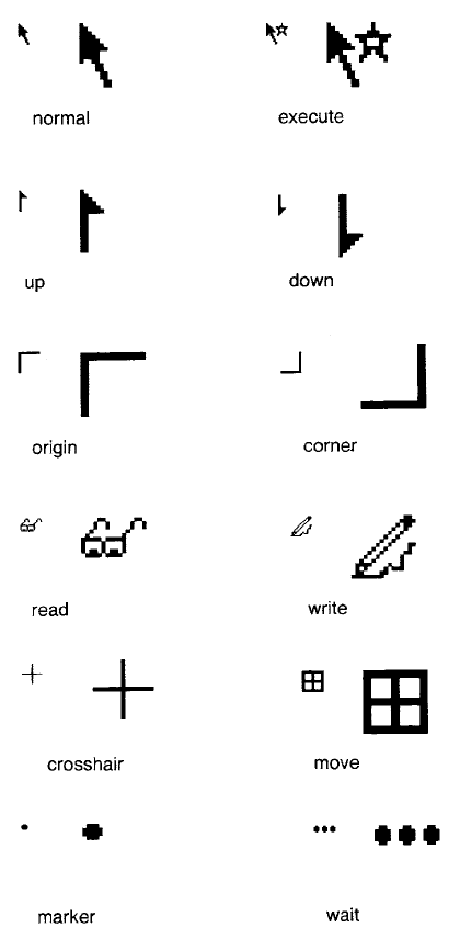
Several different cursors are supplied with the standard Smalltalk-80 system. They are shown in Figure 20.4 both small and enlarged in order to illustrate their bitmaps. The name of each cursor, given below its image, is the same as the message to class Cursor which accesses that particular Cursor. For example, the following expression shows a cursor that looks like eyeglasses on the screen while the system computes the factorial of 50. It then reverts to showing the original cursor shape.
Cursor read showWhile: [50 factorial]
Changing the cursor shape is a very effective way of communicating with the user. Attention is always on the cursor, and changing its shape does not alter the appearance of the display.
The Display Screen
DisplayScreen is another subclass of Form. There is usually only one instance of DisplayScreen in the system. It is referred to as Display, a global variable used to handle general user requests to deal with the whole display screen. In addition to the messages it inherits from its superclasses, DisplayObject, DisplayMedium, and Form, DisplayScreen provides class protocol for resetting the width, height, and displayed image of the screen.
The one case when multiple instances of DisplayScreen may exist is when (double-buffered) full screen animation is being done by alternating which instance of DisplayScreen supplies bits to the display hardware. Typically, full screen animation is not used, rather, animation is done within a smaller rectangular area. A hidden buffer of bits is used to form the next image. Each new image is displayed by copying the bits to the rectangular area using the copyBits: message of a BitBlt.
DisplayText
The second subclass of DisplayObject is class DisplayText. An instance of Text provides a font index (1 through 10) and an emphasis (italic, bold, underline) for each character of an instance of String. DisplayText consists of a Text and a TextStyle. A TextStyle associates each font index with an actual font (set of glyphs). In addition to representing this mapping to the set of fonts, a DisplayText supports the ability to display the characters on the screen. It does not support the protocol needed to create a user interface for editing either the characters or the choice of fonts and emphasis; this protocol must be supplied by subclasses of DisplayText.
Paths
A third subclass of DisplayObject is class Path. A Path is an OrderedCollection of Points and a Form that should be displayed at each Point. Complex images can be created by copying the Form along the trajectory represented by the Points.
Class Path is the basic superclass of the graphic display objects that represent trajectories. Instances of Path refer to an OrderedCollection and to a Form. The elements of the collection are Points. They can be added to the Path (add:); all Points that are described by some criterion can be removed from the Path (removeAllSuchThat:); and the Points can be enumerated, collected, and selected (do:, collect, and select:).
| accessing | |
| form | Answer the Form referred to by the receiver. |
| form: aForm | Set the Form referred to by the receiver to be aForm. |
| at: index | Answer the Point that is the indexth element of the receiver's collection. |
| at: index put: aPoint | Set the argument, aPoint, to be the indexth element of the receiver's collection. |
| size | Answer the number of Points in the receiver's collection. |
| testing | |
| isEmpty | Answer whether the receiver contains any Points. |
| adding | |
| add: aPoint | Add the argument, aPoint, as the last element of the receiver's collection of Points. |
| removing | |
| removeAllSuchThat: aBlock | Evaluate the argument, aBlock, for each Point in the receiver. Remove those Points for which aBlock evaluates to true. |
| enumerating | |
| do: aBlock | Evaluate the argument, aBlock, for each Point in the receiver. |
| collect: aBlock | Evaluate the argument, aBlock, for each Point in the receiver. Collect the resulting values into an OrderedCollection and answer the new collection. |
| select: aBlock | Evaluate the argument, aBlock, for each Point in the receiver. Collect into an OrderedCollection those Points for which aBlock evaluates to true. Answer the new collection. |
| Path instance protocol | |
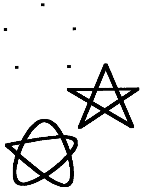
As an example, we create a "star" Path, and display a dot-shaped Form, referred to by the name dot, at each point on that Path.
aPath ← Path new form: dot.
aPath add: 150 @ 285.
aPath add: 400 @ 285.
aPath add: 185 @ 430.
aPath add: 280 @ 200.
aPath add: 375 @ 430.
aPath add: 150 @ 285.
aPath display
The resulting image is shown as the first path in Figure 20.5.
There are three paths in Figure 20.5.
- an instance of Path, created as indicated above
- an instance of LinearFit, using the same collection of Points
- an instance of Spline, using the same collection of Points
A LinearFit is displayed by connecting the Points in the collection, in order.
aPath ← LinearFit new form: dot.
aPath add: 150 @ 285.
aPath add: 400 @ 285.
aPath add: 185 @ 430.
aPath add: 280 @ 200.
aPath add: 375 @ 430.
aPath add: 150 @ 285.
aPath display
The Spline is obtained by fitting a cubic spline curve through the Points, again, in order. The order in which the Points are added to the Path significantly affects the outcome.
aPath ← Spline new form: dot.
aPath add: 150 @ 285.
aPath add: 400 @ 285.
aPath add: 185 @ 430.
aPath add: 280 @ 200.
aPath add: 375 @ 430.
aPath add: 150 @ 285.
aPath computeCurve.
aPath display
LinearFit and Spline are defined as subclasses of Path. In order to support the protocol of DisplayObject, each of these subclasses implements the message displayOn:at:clippingBox:rule:mask:.
Straight lines can be defined in terms of Paths. A Line is a Path specified by two points. An Arc is defined as a quarter of a circle. Instances of class Arc are specified to be one of the four possible quarters; they know their center Point and the radius of the circle. A Circle, then, is a kind of Arc that represents all four quarters. Again, in order to support the protocol of DisplayObject, each of these three classes (Line, Arc, and Circle) implements the messages displayOn:at:clippingBox:rule:mask:.
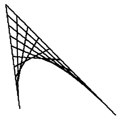
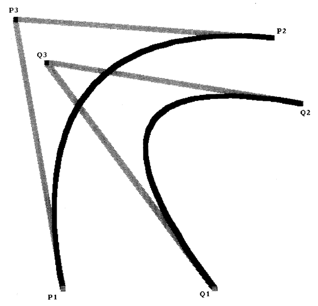
Class Curve is a subclass of Path. It represents a hyperbola that is tangent to lines determined by Points p1, p2 and p2, p3, and that passes
through Points p1 and p3. The displaying message for Curve is defined as shown in the method below.
displayOn: aDisplayMedium
        at: aPoint
        clippingBox: aRectangle
        rule: anInteger
        mask: aForm
    | pa pb k s p1 p2 p3 line |
    line ← Line new.
    line form: self form.
    self size < 3 ifTrue: [self error: 'Curves are defined by three points'].
    p1 ← self at: 1.
    p2 ← self at: 2.
    p3 ← self at: 3.
    s ← Path new.
    s add: p1.
    pa ← p2 - p1.
    pb ← p3 - p2.
    k ← 5 max: pa x abs + pa y abs + pb x abs + pb y abs // 20.
    "k is a guess as to how many line segments to use to approximate the curve."
    1 to: k do:
        [ :i | s add:
            pa*i//k + p1*(k-i) + (pb*(i-1)//k + p2*(i-1))//(k-1)].
    s add: p3.
    1 to: s size do:
        [ :i |
            line at: 1 put: (s at: i).
            line at: 2 put: (s at: i + 1).
            line displayOn: aDisplayMedium
                at: aPoint
                clippingBox: aRectangle
                rule: anInteger
                mask: aForm]
The algorithm was devised by Ted Kaehler. Basically the idea is to divide the line segments p1, p2 and p2, p3 into 10 sections. Numbering the sections as shown in the diagram, draw a line connecting point 1 on p1, p2 to point 1 on p2, p3; draw a line connecting point 2 on p1, p2 to point 2 on p2, p3; and so on. The hyperbola is the path formed from p1 to p3 by interpolating along the line segments formed on the outer shell.
Several curves are shown in Figure 20.6. The curves are the black lines; the gray lines indicate the lines connecting the points that were used to define the curves.
Two Curves were used to create the image shown in Figure 20.3. The Form was one of the images of the gentleman used in Figure 20.2.
Image Manipulation with Forms
We have shown in Chapter 18 how BitBlt can copy shapes and how repeated invocation can synthesize more complex images such as text and lines. BitBlt is also useful in the manipulation of existing images. For example, text can be made to look bold by ORing over itself, shifted right by one pixel. Just as complex images can be built from simple ones, complex processing can be achieved by repeated application of simple operations. In addition to its obvious manisfestation in the DisplayObject protocol, the power of BitBlt is made available for manipulating images through such messages as copy:from:in:rule:.
We present here four examples of such structural manipulation: magnification, rotation, area filling, and the Game of Life.
Magnification
A simple way to magnify a stored Form would be to copy it to a larger Form, making a big dot for every little dot in the original. For a height h and width w, this would take h*w operations. The algorithm presented here (as two messages to class Form) uses only a few more than h + w operations.
magnify: aRectangle by: scale
    | wideForm bigForm spacing |
    spacing ← 0 @ 0.

    wideForm ←
        Form new
            extent: aRectangle width * scale x @ aRectangle height.
    wideForm
        spread: aRectangle
        from: self
        by: scale x
        spacing: spacing x
        direction: 1 @ 0.
    bigForm ← Form new extent: aRectangle extent * scale.
    bigForm
        spread: wideForm boundingBox
        from: wideForm
        by: scale y
        spacing: spacing y
        direction: 0 @ 1.
    ↑bigForm
spread: rectangle
        from: aForm
        by: scale
        spacing: spacing
        direction: dir
    | slice sourcePt |
    slice ← 0 @ 0 corner: dir transpose * self extent + dir.
    sourcePt ← rectangle origin.
    1 to: (rectangle extent dotProduct: dir) do:
        [ :i |
            "slice up original area"
            self copy: slice
                from: sourcePt
                in: aForm
                rule: 3.
            sourcePt ← sourcePt + dir.
            slice moveBy: dir * scale].
    1 to: scale - spacing - 1 do:
        [ :i |
            "smear out the slices, leave white space"
            self copy: (dir corner: self extent)
                from: 0 @ 0
                in: self
                rule: 7]
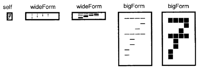
The magnification proceeds in two steps. First, it slices up the image into vertical strips in wideForm separated by a space equal to the magnification factor. These are then smeared, using the ORing function, over the intervening area to achieve the horizontal magnification. The process is then repeated from wideForm into bigForm, with horizontal slices separated and smeared in the vertical direction, achieving the desired magnification. Figure 20.7 illustrates the progress of the above algorithm in producing the magnified "7".
Rotation
Another useful operation on images is rotation by a multiple of 90 degrees. Rotation is often thought to be a fundamentally different operation from translation, and this point of view would dismiss the possibility of using BitBlt to rotate an image. However, the first transformation shown in Figure 20.8 is definitely a step toward rotating the image shown; all that remains is to rotate the insides of the four cells that have been permuted. The remainder of the figure shows each of these cells being further subdivided, its cells being similarly permuted, and so on. Eventually each cell being considered contains only a single pixel. At this point, no further subdivision is required, and the image has been faithfully rotated.
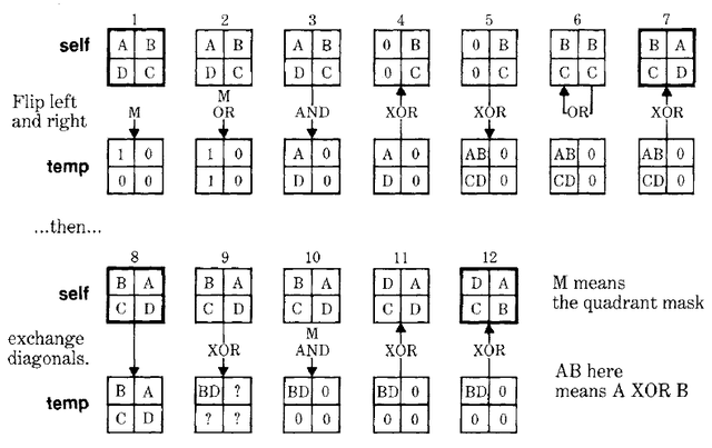
Each transformation shown in Figure 20.8 would appear to require successively greater amounts of computation, with the last one requiring several times more than h*w operations. The tricky aspect of the algorithm below is to permute the subparts of every subdivided cell at once, thus performing the entire rotation in a constant times log2(h)operations. The parallel permutation of many cells is accomplished with the aid of two auxiliary Forms. The first, mask, carries a mask that selects the upper left quadrant of every cell; the second, temp, is used for temporary storage. A series of operations exchanges the right and left halves of every cell, and then another series exchanges the diagonal quadrants, achieving the desired permutation.
rotate
    | mask temp quad all |
    all ← self boundingBox.
    mask ← Form extent: self extent.
    temp ← Form extent: self extent.
    mask white. "set up the first mask"
    mask black: (0@0 extent: mask extent // 2).
    quad ← self width // 2.
    [quad > = 1] whileTrue:
        ["First exchange left and right halves"
        temp copy: all from: 0@0 in: mask rule: 3.
        temp copy: all from: 0@quad negated in: mask rule: 7.
        temp copy: all from: 0@0 in: self rule: 1.
        self copy: all from: 0@0 in: temp rule: 6.
        temp copy: all from: quad@0 in: self rule: 6.
        self copy: all from: quad@0 in: self rule: 7.
        self copy: all from: quad negated@0 in: temp rule: 6.
        "then flip the diagonals"
        temp copy: all from: 0@0 in: self rule: 3.
        temp copy: all from: quad@quad in: self rule: 6.
        temp copy: all from: 0@0 in: mask rule: 1.
        self copy: all from: 0@0 in: temp rule: 6.
        self copy: all from: quad negated@quad negated in: temp rule: 6.
        "Now refine the mask"
        mask copy: all from: (quad//2)@(quad//2) in: mask rule: 1.
        mask copy: all from: 0@quad negated in: mask rule: 7.
        mask copy: all from: quad negated@0 in: mask rule: 7.
        quad ← quad // 2]
Figure 20.9 traces the state of temp and self after each successive operation.
In the Figure 20.9, the offsets of each operation are not shown, though they are given in the program listing. After twelve operations, the desired permutation has been achieved. At this point the mask evolves to a finer grain, and the process is repeated for more smaller cells. Figure 20.10 shows the evolution of the mask from the first to the second stage of refinement.
The algorithm presented here for rotation is applicable only to square forms whose size is a power of two. The extension of this technique to arbitrary rectangles is more involved. A somewhat simpler exercise is to apply the above technique to horizontal and vertical reflections about the center of a rectangle.
Area Filling
A useful operation on Forms is to be able to fill the interior of an outlined region with a halftone mask. The method given here takes as one argument a Point that marks a location in the interior of the region. A mark is placed at this location as a seed,and then the seed is smeared (in all four directions) into a larger blob until it extends to the region boundary. At each stage of the smearing process, the original Form is copied over the blob using the "erase" rule. This has the effect of trimming any growth which would have crossed the region borders. In addition, after every ten smear cycles, the resulting smear is compared with its previous version. When there is no change, the smear has filled the region and halftoning is applied throughout.
shapeFill: aMask interiorPoint: interiorPoint
    | dirs smearForm previousSmear all cycle noChange |
    all ← self boundingBox.
    smearForm ← Form extent: self extent.
    "Place a seed in the interior"
    smearForm valueAt: interiorPoint put: 1.
    previousSmear ← smearForm deepCopy.
    dirs ← Array with: 1@0 with: -1@0 with: 0@1 with: 0@-1.
    cycle ← 0.
    ["check for no change every 10 smears"
        (cycle ← cycle + 1)\\10 = 0 and:
            [previousSmear copy: all
                from: 0@0
                in: smearForm
                rule: Form reverse.
            noChange ← previousSmear isAllWhite.
            previousSmear copy: all from: 0@0 in: smearForm rule: Form over.
            noChange]]
                whileFalse:
                    [dirs do:
                        [dir |
                            "smear in each of the four directions"
                            smearForm copy: all
                                from: dir
                                in: smearForm
                                rule: Form under.
                            "After each smear, trim around the region border"
                            smearForm copy: all from: 0@0 in: self rule: Form erase]].
    "Now paint the filled region in me with aMask"
    smearForm displayOn: self
                    at: 0@0
                    clippingBox: self boundingBox
                    rule: Form under
                    mask: aMask
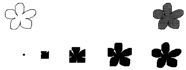
Figure 20.11 shows a Form with a flower-shaped region to be filled. Successive smears appear below, along with the final result.
The Game of Life
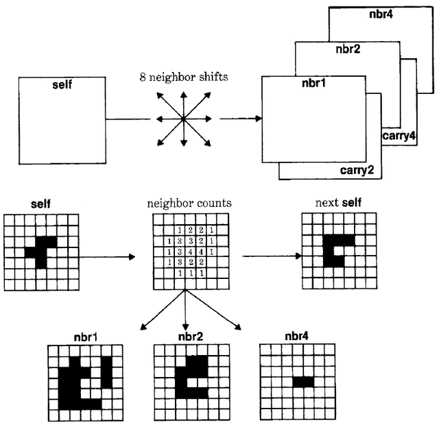
Conway's Game of Life is a simple rule for successive populations of a bitmap. The rule involves the neighbor count for each cell how many of the eight adjacent cells are occupied. Each cell will be occupied in the next generation if it has exactly three neighbors, or if it was occupied and has exactly two neighbors. This is explained as follows: three neighboring organisms can give birth in an empty cell, and an existing organism will die of exposure with less than two neighbors or from overpopulation with more than three neighbors. Since BitBlt cannot add, it would seem to be of no use in this application. However BitBlt's combination rules, available in the Form operations, do include the rules for partial sum (XOR) and carry (AND). With some ingenuity and a fair amount of extra storage, the next generation of any size of bitmap can be computed using a constant number of BitBlt operations.
nextLifeGeneration
    | nbr1 nbr2 nbr4 carry2 carry4 all delta |
    nbr1 ← Form extent: self extent.
    nbr2 ← Form extent: self extent.
    nbr4 ← Form extent: self extent.
    carry2 ← Form extent: self extent.
    carry4 ← Form extent: self extent.
    all ← self boundingBox.
    1 to: 8 do:
        [ :i |
            "delta is the offset of the eight neighboring cells"
            delta ← ((#(-1 0 1 1 1 0 -1 -1) at: i)
                @ (#(-1 -1 -1 0 1 1 1 0) at: i)).
            carry2 copy: all from: 0@0 in: nbr1 rule: 3.
            carry2 copy: all from: delta in: self rule: 1. "AND for carry into 2"
            nbr1 copy: all from: delta in: self rule: 6. "XOR for sum 1"
            carry4 copy: all from: 0@0 in: nbr2 rule: 3.
            carry4 copy: all from: 0@0 in: carry2 rule: 1. "AND for carry into 4"
            nbr2 copy: all from: 0@0 in: carry2 rule: 6. "XOR for sum 2"
            nbr4 copy: all from: 0@0 in: carry4 rule: 6].
    "XOR for sum 4(ignore carry into 8)"
    self copy: all from: 0@0 in: nbr2 rule: 1.
    nbr1 copy: all from: 0@0 in: nbr2 rule: 1.
    self copy: all from: 0@0 in: nbr1 rule: 7.
    self copy: all from: 0@0 in: nbr4 rule: 4
    "compute next generation"
As shown in Figure 20.12, the number of neighbors is represented using three image planes for the l's bit, 2's bit and 4's bit of the count in binary. The 8's bit can be ignored, since there are no survivors in that case, which is equivalent to zero (the result of ignoring the 8's bit). This Smalltalk-80 method is somewhat wasteful, as it performs the full carry propagation for each new neighbor, even though nothing will propagate into the 4-plane until at least the fourth neighbor.
